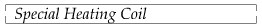
Two-piece Coils. A split-type coil like that used to heat a part
having flanges on each side of the bearing surface is illustrated in Fig. 55.
In each section of the coil are separate cooling tubes, which in turn are
series connected for the continuous flow of water. Both sections are held
together by a clamp, although various other means of connecting may be used.
One of the pieces to be heated is shown at the right of the coil.
A hinged-type inductor of solid design used for the hardening of crankshaft
bearings is illustrated in Fig. 56. The coil is arranged so that after the work
has been properly located and centralized within
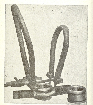
Fig. 55 - A typical single-turn heating coil of
the split type, which is used to heat the small diameter of a flanged
part.
it, the upper half of the coil is brought into contact with the lower half,
thus completing the electrical connection. Both coil sections are held together
with pressure during the heating operation. Also, both sections of the coil are
provided with internal passages for cooling purposes, with suitable quenching
chambers to make the quenching water pass directly through the area of the
coil's heating surface. The cycle for the operation is controlled by a timer
and functions as follows:
1. The coil is closed.
2. High-frequency heat is generated to the work's surface.
3. The quench is applied.
4. Finally, the coil is opened so that the work can be removed.
When applying high-frequency current to surfaces which include keyways, or
holes like those illustrated in Fig. 57, the eddy currents concentrate at the
corners, probably casing some overheating. With the keyways as shown the edges
will heat rapidly and a slight burning action might take place. To overcome
this, the part can be fitted with a copper key to bridge this gap, thus making
the heating more uniform.
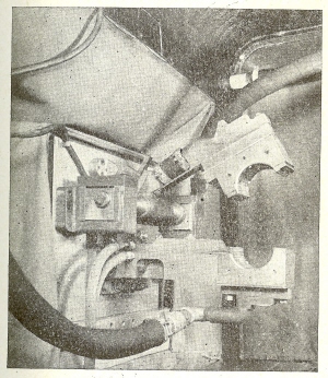
Fig. 56 - A well proportioned hinged-type
induction heating coil used for hardening crankshafts bearings.
In case a part having a hole through the surface is to be heated, as shown at
A, the magnetic flux from the coil will tend to enter the hole and develop
maximum heat around the edges. To reduce this condition the hole can be
provided with a copper plug which shunts the opening and thus reduces the
absorption of eddy currents at this point.
In heating a slotted part within a cylindrical coil, as shown at A in Fig.
58, the circulating current on the surface of the work piece naturally is
interrupted by the slot, but the current will continue to flow
Fig. 57 - Overheating of sharp corners, such as
keyways and holes, often takes place and the use of copper inserts may be
advisable to shunt the path of high frequency current.
on the inside because of the nature of high frequency, which must form a
closed circuit. When treating pats of this design, therefore, a somewhat higher
heat usually is produced at the edge of the slot, as indicated at S. With the
multi-slotted part as shown at B, the circulating current around
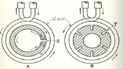
Fig. 58 - In heating shaped parts such as those
shown in this example, the high frequency current tends to crowd into the slots
resulting in overheating.
the work piece will have a tendency to crowd into the slots T, and again an
overheating condition is most likely to occur on the corners. The thinner the
coil in relation to its diameter, the more pronounced the heating at the slots.
On the other handle, with the use of a heating coil having a height greater than
its diameter, this condition will be less pronounced.
Single-turn Coils. Solid-type induction coils are made of sheet
copper, as illustrated in Fig. 59, and can be arranged for single or multiple
operation. The coil shown at A, which is typical for heating
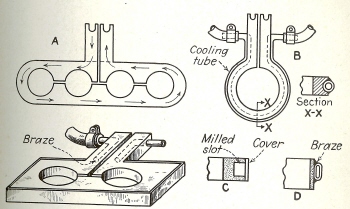
Fig. 59 - Constructional details of single-turn
coils made from flat copper plate and provided with means for
cooling.
parts simultaneously, is made of a thick copper plate, bored to provide
coupling sufficient for the diameter. Two connecting blocks are brazed to this
plate, and then the plate is sawed out, as shown, so that the high frequency
current will follow the path of the arrows, coming in at one block and going out
at the other.
At B is a single-station coil of similar design, showing a suitable method
for providing the necessary cooling. A groove is milled around the coil, and a
copper tube is brazed in place. At C is shown another solid-type inductor, in
which the cooling chamber is provided by milling a slot around the outside edge
and brazing a sheet-metal cover over it. The water outlet to the two connectors
is made by drilling a hole through them and connecting a small tube, as shown.
Another type of solid inductor is illustrated at D. This includes a band of
copper to which a section of flattened tubing is brazed to the outer edge.
In making the so-called solid-type inductors, which comprise a single-turn
coil, it is best to consider the proportions shown in Fig. 60. It will be seen
that the height of the coil is equal to one half the diameter. These
proportions can be exceeded in certain cases and various modifications are
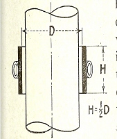
Fig. 60 - In making single-turn coils it is well
to keep the over-all height to approximately one-half the diameter as
shown.
possible, but it is usual to limit the use of solid inductors to applications
in which the height or length of the heat zone is less than the diameter of the
coil. When a longer area requires heating, multiturn coils may be used to
better advantage. If the area to be heated is exceptionally long, progressive
feeding may be the solution.
the length of the heated zone of a shaft placed within a cylindrical coil
will usually exceed the over-all height of the coil at both ends by a distance
equal to the coupling C, as shown in Fig. 61. This overlap is indicated at E in
the illustration. When the thickness of the coil T is increased, as shown,
there is a tendency for the heating zone to spread out still farther on each end
of the coil, as indicated at F. This heating action is the result of a wider
distribution of magnetic flux, which develops from a thicker heating coil. The
same condition also exists in either case, when using multiturn copper-tube
heating coils.
Miscellaneous Coils. In Fig. 81 is illustrated a flat type coil,
which has broad uses in the heating of parts requiring uniform heat. This coil
is made from a flat piece of copper. First, four holes are drilled through the
entire length, then the slots are cut as shown, so that the current will
circulate back and forth, entering through the connection at A and leaving at
the connection B. At the end of the coil, where provision is made for
circulation of the cooling water, the small plates P can be attached, as
indicated. Coils of this type can be made in various sizes and styles, and are
particularly suitable in cases where a single hairpin coil is applicable.
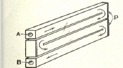
Fig. 81 - A flat-type coil made from a block of
copper, with drilled holes for passage of water and slots cut between sections
to distribute the passage of high-frequency current.
The coil shown in Fig. 82 is used for the heating of the end of a drawn cup
which requires forging. The coil in this case is made from a strip of copper,
to which a cooling tube is brazed, as may be seen. The area of the part to be
heated is approximately 2 in. in length and the temperature required is
1800˚F. The coupling of the coil is approximately 3/16 in.
In using coils of this type, a very even distribution of
heat can be produced, but solid coils of the same type are limited in their
height. The proportions shown in this particular coil are very satisfactory,
however, and the example is representative of the possibility of providing a
high temperature heat to a localized surface. In other methods it should be
necessary to heat the entire part, which often is objectionable. With
high-frequency heating the temperature change is so localized and so quickly
applied that the part can be removed by hand and inserted into the forging press
without insulating precautions that normally would be required.
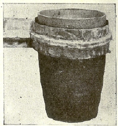
Fig. 82 - A large single-turn coil used for
heating the end of a drawn steel shell, for a forging operation.
A single-turn coil used for soldering a socket to a reflector is illustrated
in Fig. 83. The socket is assembled to the reflector body and a ring of solder
is placed in the joint. Because of the thickness of the joint of the parts to
be heated, the heat is quickly applied and as a rule the coupling of the coil
can be made somewhat greater then for the average heating operation,
particularly where a greater
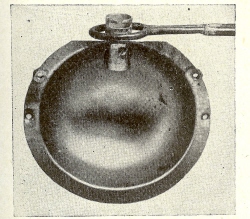
Fig. 83 - A small single-turn coil used for the
soldering of a socket to a reflector.
mass of metal is to be considered. The spacing of the joint where the coil
meets should be held to a minimum, so that even distribution of flux density
will prevail. Soldering operations of this kind can be effectively handled in
multiple, using a series-type coil.
In Fig. 84 is shown a double hairpin-type coil used for joining a steel
ring. This coil practically
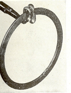
Fig. 84 - A double hairpin-type coil used for
the joining of a steel ring.
surrounds the surface to which heat is to be applied, as will be seen. A
soil of this type can be made to heat a wide variety of surfaces and because of
its simplicity in design can be quickly formed.
Sometimes it is necessary to apply heat to the corners of an assembly such as
shown at A in Fig. 85. In this case an analysis has to be made of the
magnetic-flux dissipation from the coil to insure uniform heating. The use of a
hairpin coil, as shown at B, would result in the absorption of some of the
energy on the end plate C rather than in the corner. This would indicate that
the coil should be provided with a formed end as shown at D, in order to provide
for an extra amount of flux to this corner area.
On other parts presenting a similar condition, it would be possible to use a
coil formed on the end, as shown at E. Still another way to insure maximum flux
density in corners is to make a heating inductor as illustrated at F. In this
design, the ends of the connecting tubing are fastened to a small copper block.
This block is provided with a saw cut at G, so that the high-frequency current
will pass down to the corners. The end of the block is milled out for the
circulation of cooling water, as shown at H. A cover plate is then attached to
the face of the block to complete its structure.
In Fig. 86 is represented a piece of work requiring the heating of three
inserts for brazing purposes, for which a specially formed coil should be
provided. Assuming, however, that a symmetrical coil were used, as shown at the
upper portion of the illustration, there would be a tendency for the
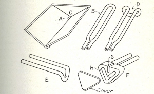
Fig. 85 - When heat has to be thrown into a
corner, it is usually necessary to provide a coil which will transfer an extra
amount of heat to this joint.
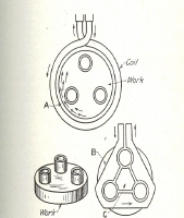
Fig. 86 - Principles involved in brazing three
lugs to a cap by means of a single-turn coil, showing the correct and incorrect
methods.
circulating current to crowd through the narrow portion of the work, as shown
at A, and excessive heating would take place. Also, there would be insufficient
heat at the inside portion of the insert.
To handle such an operation a series-type heating coil, as shown at B would
be required. In that case the high-frequency current would enter at one
connection, then completely surround the three inserts, and pass out through the
other connection. It would be necessary, however, to use a coil inset, as shown
at C, which would act as a flux concentrator. In making such a coil it would be
necessary to provide cooling not only for the outer section, but also for the
insert.
When hardening the outer surface of a part having a variation in depth, such
as the sprocket shown in Fig. 87, there would be a tendency for the outer
portion of the teeth to absorb more heat than at
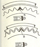
Fig. 87 - When heating irregular surfaces such
as sprocket teeth, it is essential to use a formed coil, usually of the cast
type, in order to assure uniform heating.
the root. Assuming that a single-turn flat-type induction coil were used, we
would get a heat pattern such as that shown at A, on which the points might
become overheated. To overcome this condition, the coil should be made to
conform to the approximate outline of the teeth, like that shown in the lower
portion of the illustration. A coil of this type can be cast to size and with a
carefully made pattern should require very little cleaning to assure uniform
heat. With a formed coil of this type, the heated zone will be produced as
shown at B, with a more uniform density of heat around the entire profile of the
tooth, especially at the root.
Sometimes it is necessary to provide a tubular-type coil for maximum heat
concentration to the surface of a part, where a solid-type inductor might be
preferred to a multiturn coil. The design of a coil for such an operation is
illustrated in Fig. 88. A copper tube of the size required is cut off as shown
at A, then a section of small tubing is wound around the outside, as illustrated
at B. Finally the coil is saw-cut with a spiral, as shown at C.
An induction-coil assembly for the heating of continuous strip this coil is
longer in relation to its diameter than would normally be necessary for
hardening operations, but in cases where continuous heating of material is
desired, a coil of this type works satisfactorily. In this application, the
heating-coil unit is placed adjacent to a power press. The material being
heated is a magnet-steel strip which is heated to 1800˚F, then
blanked, formed, and hardened in one operation. The temperature attained in the
steel as it enters the press is slightly higher than that required for
hardening, but during the blanking and forming operation the temperature drops
to approximately 1525˚F, then quenched in oil. The steel is 1/8 by 5/8 in. in
size and is heated by a 30 kva input high-frequency unit. As a result of
high-frequency heating, the steel receives a higher indexing magnetism and a
better magnet is produced. Another direct saving is a marked reduction, or
practical elimination, or rejects.
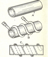
Fig. 88 - Constructional details of a
spiral-type coil made of a copper sleeve to which copper tubing is attached for
cooling purposes.
Flexible leads can be used with induction heating setups, although their
application should be limited to heating requirements which might make them
necessary. These leads can be made from sections of high-pressure metallic
tubing of the flexible type, as illustrated at A in Fig. 90. It is essential,
however, that the braided cover, as well as the inner bellows, be made of a pure
copper, having high electrical-conductivity qualities. For safety it is well to
provide a rubber hose on the outside, as indicated. Leads of this kind provide
for the passage of high-frequency current from the generator to the work coil,
as well as for the passage of cooling water.
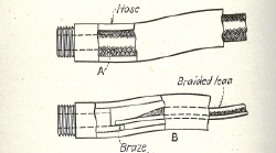
Fig. 90 - Two types of flexible leads which can
be used in connection with induction-heating generators.
Another way to make a flexible lead is illustrated at B. Here the
braided-copper lead is brazed to the connector and then covered by a rubber hose
as shown. With this type of lead, it is necessary to have a similar connection
at the other end for attaching the work coil.
In Fig. 91 is illustrated a multiturn coil provided with insulating in the
form of woven glass sleeving. About the only advantage of insulation of this
type is the elimination of metal-to-metal contact of the coil windings, which in
this case are very close together. Where intense heat is to be applied,
however, insulating material of this kind does not give long service and other
means of insulation are more practical. A copper-tube coil can be lacquered,
or coated with insulating varnish, then baked, if its use is not in connection
with flux as used for brazing. Plating is not usually recommended, since
high-frequency current travels on the surface of a coil, and plating materials,
such as chrome, are not good conductors. Ceramic cement provides good
insulation around a coil and may be used where protection is desired.
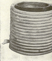
Fig. 91 - A multiturn heating coil covered with
woven-glass sleeving. Coil insulation can also be obtained by applying a baked
coat of insulating varnish.
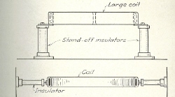
Fig. 92 - Large heating coils can be supported
by stand-off insulators, in order to assure rigid mounting.
Heating coils sometimes require outboard-supports, because of their sizes and
shapes. While such supports can be provided in various ways, it usually is best
to consider an insulator that will prevent the loss of high-frequency current
from the coil. A satisfactory type of support is a stand-off insulator, as
illustrated in Fig. 92. Small extensions can be brazed to the bottom, so that
a rigid coil mounting is provided. It also is possible to support induction
heating coils from their sides, as shown in the lower portion of the
illustration. In this case, the end of the stand-off insulator is brazed to the
side of the coil, then the base of the insulator is mounted to some convenient
vertical support at the sides.
Many other forms of brackets and supports can be used for coils and, in cases
where insulating material such as asbestos board is used for the top of a work
table, there is no objection to providing copper feet or legs in the coils for
alignment purposes. Other means of supporting coils may be seen in various
illustrations showing hardening and brazing installations.
|