
The coil used for heating the inner surface of a
rocker arm which required hardening the coil comprises two turns positioned so
that they lie adjacent to the surface requiring heating.
A good many applications of induction heating require the use of coils which
might have two or more windings spaced widely apart to suit surfaces of varying
size. In this case it is important that the paths of the current flow in the
same direction. Assuming that a double-turn coil is desired, like that shown at
A in Fig. 63, the winding arrangement should be such that the current flows in
the same direction, as indicated by the arrows. If a coil were made such as
that as shown at B, with the current flowing in one direction in one coil and
opposite in the other, the magnetic flux of one would have a tendency to cancel
that of the other, so that practically no heating would result. This is an
important consideration in the construction of coils of this type, particularly
where multiturn and series type heating coils are needed.
A multiturn coil of the series type arranged for hardening two surfaces is
illustrated in Fig. 64. While applications of this type can be provided for as
shown, there are bound to be some losses due to the length of the leads between
each coil section and, before the adoption of multiple heating as illustrated,
the advisability of hardening the surfaces separately should be considered. In
any case, a coil of this type should be so arranged that the leads are close
together and never as indicated by the dotted lines, for the inductance
resulting from the jumper and the input leads which would cause heat losses.
Fig. 63 - When making series-type coils,
particularly those of the flat type, it is essential that all turns be made to
carry the current in the same direction, as shown at the left.
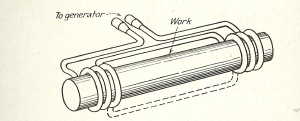
Fig. 64 - In constructing a series-type coil as
shown here, it is important that the leads be kept close together in order to
assure maximum heating to the areas on which heat is required.
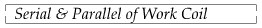
Fig. 65 - A series-type coil assembly,
comprising four multiturn coils, arranged for internal heating.
Multiturn copper tube coils of the series type can be made of a single piece
of tubing, as has been shown, whereas another practical design is that shown in
Fig. 65. Here the coils are made separately and joined together by bus bar
jumpers, or connectors. The hose shown at the top is used for providing a
continuous flow of water through all four coils. The two supporting members,
through which the copper tubing is assembled, are made of asbestos board.
In Fig. 66 is illustrated a series-type internal-heating coil showing another
means of making a connection. Each coil is made separately and then connected
to a jumper plate A, through
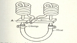
Fig. 66 - Double-type internal-heating coils
arranged with a bus-bar connector and a hose for the continuous passage of
water.
which the high frequency current passes from one coil to another. The ends
of the coil tubing are then connected with a section of hose, to provide
continuous passage of cooling water. The other two ends of the coils are
connected to the output leads of the high-frequency generator. This design can
be used for a greater number of coils, which may have to be joined together and,
where operating conditions permit, operated in series.
A multiturn coil used for brazing together two steel sections in which heat
is desired from the inside surface is illustrated in Fig. 67. The part has been
cut in half to show the relative location of the coil. When long leads are
required, as is true in this case, it is necessary to keep the leads close
together, particularly where they enter the bottom opening, like that shown. It
must be remembered
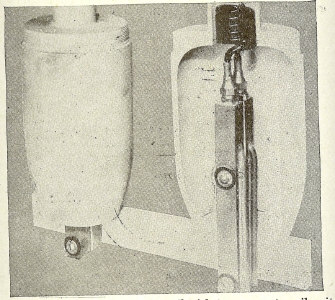
Fig. 67 - A series-type internal-heating coil
with two separate coil units, which is used for the brazing of two steel cases
simultaneously.
that if the leads lie adjacent to a metallic surface, thy will generate heat
where it may not be wanted and dissipate some of the energy needed for a
particular portion. In this case, the leads are mounted in insulating blocks
attached together but separated by mica insulation. for the operation shown,
the two pieces are handled in one setting and the two coils are series
connected. All lead connections are made on the underneath side of the table
The coils shown in Fig. 68 is an excellent example of a solid-type inductor
for heating two parts at one time. The coil is made from a plate of copper 3/8
in. thick and bored out to provide suitable clearance around the two work pieces
to be heated. The copper tube, used for cooling, may be seen around the outside
edge of the coil. The coil is supported by two angle plates connected to the
front panel of the worktable. Since the panel is made of insulating material,
the brackets have no means of shorting the high-frequency current. When making
supports for coils it is important to provide proper insulation. The coil is
used for brazing two steel tubular parts together, like those shown at the
right.
A series-type coil made from several copper bushings attached together
around the upper and lower portions of the bushing are brazed the copper tubes
used for cooling.
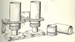
Fig. 68 - Tandem design heating coil of the
single-turn type used for the brazing of steel tube assemblies.
Saw cuts are provided between the bushings in order to provide for a
continuous path of high frequency current. The operation in this case is the
brazing of a steel tube to a cap. The coil and fixture are arranged so that
eight parts are completed simultaneously. A coil of this type is relatively
easy to build and may be employed in a variety of operations requiring
multi-setups.
The same general principle is applied to series - type coils made from a flat
copper plate, like the one illustrated in Fig. 70. Here the cooling tube is
brazed on the underneath side of the plate and shaped to conform to the coil
openings. The tubing connections are brought out at one side, to provide a
suitable connection to the output leads of the generator. The coil is provided
with small end plates, as at A, to which supporting braces can be attached, to
provide for rigid mounting.
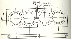
Fig. 70 - A heating coil made from a flat copper
plate and provided with a cooling tube, placed on the underneath side, is
illustrated above.

High-frequency current will circulate around the surface of the metal part
even though this is not completely surrounded by a coil. Naturally there are
limits in the extent to which this principle can be applied, but for average
small parts, usually requiring high-frequency heating, it is possible to use two
parallel inductors and to pass the work underneath, or arrange it in approximate
relation to the inductors, so that heat will be absorbed around its entire outer
surface. This principle is illustrated in Fig.76. Here, at A may be seen the
relation of two parallel inductors used for soldering a cover plate to the body
of a round condenser can. In this case the heat is
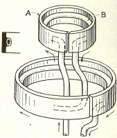
Fig. 75 - Another form of series type internal
heating coil. Copper tubing is used for connecting both sections, as well as to
provide for the flow of cooling water.
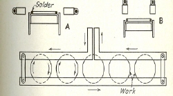
Fig. 76 - An example of parallel-type inductor,
comprising two bars, which is used for the soldering of condenser
ans.
concentrated to the edges only. For the example
shown at B, the inductor bars are located directly above the joints to be
soldered, which in some cases will be found preferable. The principle of
heating is shown below. It will be seen that the high-frequency current
circulates through the bars of the coil which, in turn, is induced into the work
located underneath in the opposite direction. In handling operations of this
kind, the work can either be placed in a fixture that provides correct relation
to the inductors, or conveyor-fed progressively under the inductors.
Another form of inductor, comprising two bars, is illustrated in Fig. 77.
Here the longer bar A is adjustable by means of the jumpers B. As will be seen,
the bars are provided with cooling
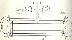
Fig. 77 - A two-bar parallel inductor of the
adjustable type is shown above.
tubes and have hose connections at their ends for the continuous passage of
cooling water.
The coil shown in fig. 78 also is of the two-bar type and is arranged so that
work can be passed through the opening, as illustrated at A. The part
represents the end of a drawn-steel shell which requires annealing. The
operation is performed by feeding and rotating the work through the bars,
starting at one end and leaving at the other. In mounting coils of this type,
it is necessary to provide suitable supports, such as stand-off insulators, in
order that rigid mounting can be obtained.
In Fig. 79 is illustrated a two-bar inductor of the parallel type used for
the heating of a long steel bar requiring hardening at one edge only. In this
example the inductors are cut out to conform to the shape of the part, as shown
in the cross-sectional view at A. Holes are drilled lengthwise through the
inductors for the passage of cooling water. At one end a jumper is provided,
whereas at the other end of each bar the terminals connected with the generator
are brought out. Coils of this type can be insulated by means of mica, in which
case it is possible to provide a means for clamping them firmly together. The
sectional view taken through the inductors shows the work in the heating
position. Only the edge of the bar is heated as it is progressively fed through
the inductors. A spray
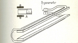
Fig. 78 - A two-bar-type inductor arranged so
that the work can be rolled between the plates as may be required for annealing
the ends of shells or tubes.
quench unit, not shown, is located at the left of the inductor, in order to
complete the hardening cycle.
In making heating coils for continuous feed operations, it is often desirable
to use copper tubing
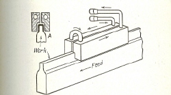
Fig. 79 - A solid-type parallel inductor used
for the transfer of heat to the edge of a long shear blade, requiring
progressive hardening.
made into the form of a hairpin, under which the parts to be heated are fed.
With such a coil it is often necessary to bend the end of the coil upward, as
illustrated in Fig. 80. If the coil remains on a true horizontal plane, as
illustrated at A, there may be a likelihood of excess heating on the edge of
the work, as at B, especially is sharp corners are encountered. Usually the
thinner the work, the more necessary it is to provide this bend at the end of
the coil.
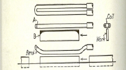
Fig. 80 - When using hairpin-type coils for
heating the edge of narrow strips, it is advisable to turn the end of the coil
upward to avoid overheating on the corners of the work.
|