Coils for high frequency induction heating can be made in a wide variety of
styles, shapes, and sizes. Their design usually is governed by the nature of
the component to be heated and by the type of generator used. Briefly, coils
can be of the single-turn or multiturn type, fabricated, multiple,
series-connected, or cast to shape. However, some high frequency generators are
limited to certain specific types of coils, because of the impedance of their
tank circuits which may limit their use to multiturn coils. In view of this
condition, the power source must be taken into account before a heating coil is
designed. Other generators, however, are provided with means to match
practically any type of heating coil so that a much broader selection of coil
designs is made possible.
In describing different types of heating coil for inductive operations, it
would be difficult to cover all the different types of condition which arise,
such as the shape and size of the work piece, the nature of the surface to be
heated, and its relation to the heating coil. However, from the variety of
heating coils shown, representing the designs most commonly used, together with
some of the basic principles involved, a good conception of the importance of
coil construction will be gained. The designs represent coils that will service
the need for a wide variety of heating operations, and that with slight
modifications will cove the majority of heating applications encountered.
Perhaps nothing is more important to induction heating than the coil itself.
Next is the source of power, which must be suited to particular operation
contemplated. It is here that frequency and volume of power show their
possibilities as well as their limitations. But with suitable high frequency
power it is on the coil that we depend for the correct distribution of heat
within a metal part.
If we consider a heating coil as a means of transferring heat by eddy
currents, and then consider the shape of the coil in relation to the work's
surface, we can see that the heat pattern will closely resemble the shape of the
coil, more so with a close coupling than where the work and the coil are farther
apart. The problem therefore is to make the coil of correct shape to surround a
surface to be treated and then space it according to the amount of heat needed.
As the coil is placed farther from the work, the eddy currents spread out in
wider form and cover a larger surface. Coupling, therefore, is an important
consideration.
Not always is maximum heat transfer the most desirable factor.
Often a slow, even heat distribution is outstanding need. For general hardening
purposes a quickly and rapidly heated surface usually is desired. For soldering
a slower penetrating heat might be more desirable. For brazing a
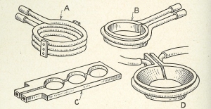
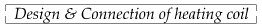
Fig. 37 - A variety of heating coils used in
connection with induction heating equipment, including those of the single and
multiturn types.
somewhat in between heat might be required, since rapid heat might cause
blistering and a slow heat would result in lost time or the heating of unwanted
areas.
Types of Coils. In Fig. 37 are illustrated some of the more commonly
used coils as applied to induction heating equipment. The general purpose type
most used is one shown at A representing the multiturn design, which is would or
formed from copper tubing, either symmetrical in contour or shaped to suite the
outline of the part to be heated. Solid-type inductor coils, like the one shown
at B, are also widely used and are particularly suitable for heating of parts
where a restricted heat zone is desired. The coil shown at C is of series
design, which makes possible the heating of several pieces at onetime. The coil
at D is made of flat strip, which, as may be seen, may be used in a variety of
heating operations.
Regardless of the types of coil used, it is necessary to provide cooing,
which in the case of the multiturn coil is accomplished by circulating a flow of
water through the coil itself. With the single-turn inductors, cooling is
accomplished by adding a copper tube to the outside or by other suitable
cavities for the passage of water.
Fig 38. - Multiturn coils can be formed to
various shapes and usually have a wide latitude of applications in connection
with induction heating work.
All heating coils, regardless of their design or shape, should be made of
copper having a conductivity of 90 per cent or more. Pure copper unquestionably
serves as the best material for coil construction.
Multiturn Coils. In making multiturn coils of copper tubing, a wide
variety of shapes is possible, as shown in Fig. 38. The most common is a
cylindrical coil, as at A, which is suited to surface-heating of shafts and
round parts. The rectangular or square coil at B, as well as the cam-formed
coil at C, also is used for heating the outer surfaces of bars or shafts and can
be easily formed and would over a wooden block. The pancake coil at D is used
for heating flat surfaces, such as clutch jaws, or ends of shafts, while the
spiral-helical coil E is used for heating conical surfaces, such as bevel
gears. The coil at F is of the internal type and is used for heating inner
surfaces of holes.
Other suggested types of induction coils made of copper tubing, arranged for
heating irregular surfaces, may be seen in Fig. 39. The coil at A heats the
surface around the slot, while the one at B heats the end section of a formed
steel bar. Coil C, somewhat similar in shape, heats on edge and the fillet of a
plate, one view of which illustrates the coil in position during heating. With
irregular surfaces such as these, requiring coils of intricate shape, it is
often necessary to experiment until
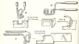
Fig. 39 - Copper tubing can be formed into
various odd-shaped coils, as shown, for the localized heating of metal
parts.
the correct heat pattern is obtained. Sometimes only the spreading of the
coil, one way or another, might offer the results desired, whereas in other
cases a completely new shape may have to be wound.
In Fig. 40 suggestions are shown for the construction of copper-tube coils.
Such coils usually are made of tubing ranging from 1/8 to 1/4 in. in diameter.
The 1/8 in. size should be used very sparingly, however, because of its small
area and since the flow of cooling water is likely to be too small to prevent
overheating. For short heating cycles, where a slight heating of the coil may
have no effect, this size could be considered. However, the two larger sizes
are preferable.
Round copper tubing can be used for many types of coils, as shown in A,
although it is usually preferable to flatten the tubing as illustrated at B.
Another practical form is the square or rectangular shape shown at C. It also
is possible to use a larger diameter tubing, such as 5/8 or 3/5 in., as shown at
D, and to produce a flat coil similar to a solid inductor previously
mentioned.
In making helical copper-tube coils where a restricted heat zone is desired,
the coils should be made with an offset, as shown at E, so that uniform heating
can be provided. At F is shown
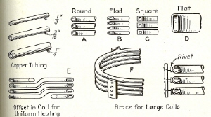
Fig. 40 - Constructional details of copper-tube
heating coils of the multiturn types are shown here.
a means of providing a brace for large-diameter coils, which might have a
tendency to sag or go out of shape. These braces provide unusual stiffness and,
as shown, are attached by brazing small rivets to the coil section and heading
the rivet over on the outside of the braces. These braces can be made of thin
asbestos board, or a laminated plastic material.
A suggested form of tube flattener for use in the making of heating coils
requiring square, oval, or other formed sections, is illustrated in Fig. 41.
This device consists of two formed rolls, through which the copper tubing is
passed. Feeding of the tubing through the rolls is done by means of the hand
crank. The upper roll is mounted on a hinged bracket, which is adjusted. to
correct relation with the lower roll by means of the hand knob B. At C is shown
the type of roll which can be used for forming a square-shaped section from a
round tube, whereas at D is illustrated the roll used for providing an oval - or
flat - shaped tubing.
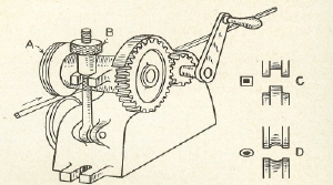
Fig. 41 - A hand - operated tube flattener,
provided with forming rolls, can be used in the construction of heating coils
requiring flat tubing.
Heating Rates. Because of the path of magnetic flux around a
cylindrical coil like that at A, Fig. 42, the greatest field strength will be
obtained within the coil itself, rather than on the outside. For this
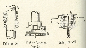
Fig. 42 - Three most popular types of multiturn
coils are the external, pancake, and internal designs shown here.
reason outside surface-heating of parts, such as steel shafts, can be
preformed exceedingly fast. With a flat- or pancake - type coil, as at B,
heating will be somewhat slower per square inch of area, or roughly 75 per cent
that of the example at A. With internal-type coils, like those shown at C, heat
transfer is still slower, because less magnetic flux is concentrated on the work
surface, and may be heated only 50 to 60 per cent as fast as outside heating.
These estimates are based on the use of a high frequency generator of a given
output power. for non-ferrous materials heating times will be somewhat greater
than for ferrous materials, usually in the order of 1 1/2 or 2 to 1.
Internal Coils. since the density of the magnetic flux is less on the
outside than on the inside of a coil, and because the greatest strength lies
next to the coil, it is advisable to make internal coils in
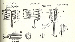
Fig. 43 - Constructional features of internal
coils are shown here. Coils of this type should be made as thin as possible and
should be located close to the work's surface.
such a way that the over-all distance from the surface of the hole being
heated to the inner surface of the coil is held to an absolute minimum. In A,
Fig. 43, is shown a multiturn coil of usual design, which, when applied within a
hole, results in the dissipation of heat energy because of the excessive
over-all depth between the work surface and the inner diameter of the coil.
At B the condition is greatly improved, since the coupling between the work
and coil is reduced and since the coil is flattened. This means that the
over-all depth is held to a minimum, thus assuring maximum heat energy, the
magnetic flux being more constricted to the heated area. The coupling for
internal heating coils should be made no more than 1/16 in., and less if
possible.
Internal cols for hole heating usually are limited in size because of their
mechanical construction, and usually a 5/8 in. hole is the smallest that can be
heated with a multiturn coil, as shown at C. Another form of internal coils is
the double-turn coil, illustrated at D, in which the tubing is flattened to
provide for maximum heat transfer. In making coils of this type, care should be
taken to avoid closing in of the tubing, so that the water passage will not be
restricted. Also, because the hat pattern within the hole is likely to resemble
four longitudinal bands, the work piece should be rotated during heating. The
coil at E provides still another design using formed tubing, thus permitting the
coil to be small in diameter.
The hairpin coil at F also is practical for small-hole heating, but the part
must be rotated during heating to assure uniformity of heat transfer. Usually
internal coils of the types shown are limited to surfaces in which the height of
the heated surface is not more than twice the diameter. Where the length is in
excess of the ratio progressive heating should be provided if possible. In this
case the heat is concentrated to a small area of the hole, while the work itself
feeds at a uniform rate, depending upon available output capacity of the
generator, the size of the hole, and the area being heated.
When heating a tapered surface, the coil is usually made to conform with the
taper, although exceptions may be considered as at A, Fig. 44, which shows a
fixed-diameter coil arranged so that the pitch of the winding is wider at the
large end than at the small end. With this design, a greater concentration of
heat will be provided at the small end, because of the variation in pitch.
It is well to remember that with a fine-pitch coil the penetration of heat
will be deeper than with one having a coarser pitch. Usually the spacing
between cols should not exceed half the diameter of the coil, while smaller
spacing is preferable.
In heating conical parts, such as bevel gears, a coil with a consistent
spacing or coupling will result in a more intense heat at the small end, as
shown at B. To compensate for this condition, the coil should be made with a
wider angle at the small end, as shown at C, so that heating will be uniformly
distributed.
The same procedure is followed when using a solid-inductor coil, shown at D.
In heating flat surfaces, like that illustrated at E, a coil made parallel to
the face will have a tendency to create the greatest heat toward the center.
Coils for such surfaces, therefore, should be made slightly conical or angular,
as shown at F.
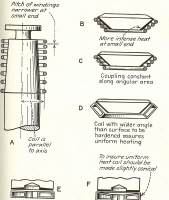
Fig. 44 - Coils provided with variations in
spacing between turns can be arranged to transfer heat uniformly to tapered
surfaces. Usually in heating tapered surfaces the coils should be made with a
wider angle than that of the work piece.
Distribution of Heat. An example of a multiturn copper-tube coil used
for hardening a projectile on which differential-hardness readings are desired
is illustrated in Fig. 45. The coil is made so that the hardness readings from
the point of the projectile to the base will taper gradually from 60 to 35
Rockwell C. In operation the part is heated and then quickly dropped into a
quench. The variation in heat and hardness is attained by a variation in
coupling, and in the pitch of the coil turns, which
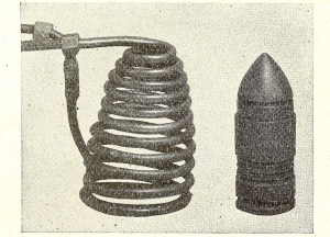
Fig. 45 - A coil provided with variations in
turn spacing, which is used for the hardening of a projectile on which a
gradient of hardness ranging from 35 to 60 Rockwell C is
obtained.
as can be seen are wider at the bottom than at the top. This type of coil
provides for maximum heat where the hardest area is desired, and gradual
diminishing of heat for less hardness.
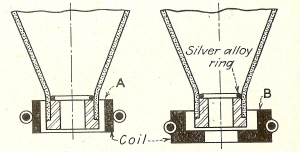
Fig. 46 - A single-turn heating coil used for
brazing a steel tube and an insert together. It is necessary to arrange the
coil so that the transfer of heat is concentrated on the heaviest section of the
assembly.
In designing coils for heating purposes, it is often necessary to analyze the
application to determine the best means of heat distribution. For the
application shown in Fig. 46, which requires the brazing of a steel insert to a
drawn-steel shell, the coils as shown at A might cause overheating of the then
material before the proper amount of heat could be conducted to the heavier
insert. This being the case, the outside surface also might blister and become
badly warped.
To overcome this condition, a coil such as that shown at B would be
desirable, since the generation of heat would be distributed more to the heavier
section, particularly at the bottom, and then would travel by conduction to the
remaining surfaces directly above. For heating operations of this kind, a solid
inductor of the single-turn, or even-series, type, is to be preferred. The coil
can be made somewhat higher than might be necessary. Then after observation of
the resulting heat the coil can be trimmed down one way or the other until the
exact heat pattern has been produced.
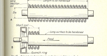
Fig. 47 - It is not good practice to make long
multiturn coils, because uneven heating is very likely to take place. In
heating long areas, it is better to use a short coil and feed the work
progressively through it.
Length of Coils. There is a limit to the length of surface which can
be heated at one time, and while no fixed rule applies, a helical coil usually
should not be more than three to four times its diameter, whereas a single-turn
coil will be found more effective when the length is not more than half the
diameter. The example shown at A in Fig. 47 obviously is too long, since too
great a surface is being heated at one time, causing possible deflection as well
as an uneven distribution of heat. For a surface of this type, assuming that
hardening is required, it would be much better to use a shorter coil and
progressively feed the part through it, such as is shown at B. The available
output power of a generator also is relative to the amount of surface that can
be heated at one time. IN this same example a generator with considerable power
would be required to heat the entire shaft at one time, as compared with one of
nominal power for the progressive-heating method.
Multiturn coils exceeding the proportions given can be sued for the heating
of this sections, such as steel wire and rod, especially in annealing
operations. For hardening and brazing requirements,
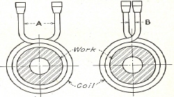
Fig. 48 - In connecting heating coils to
generators, it is well to keep the leads as close together as possible in order
to avoid inductance losses, which would detract from maximum heating in the
work.
however, exceptionally long heating cols may offer difficulties. Sometimes
it is this consideration that decides whether a job can best be performed by
inductive heating or some other method.
Inductance Losses. When connecting the leads of a heating coil to a
generator, especially those of the quick-change type, it is desirable to keep
them as close together as possible, in order to avoid inductance losses between
the leads, as might be represented by the example in Fig. 48. The spacing, as
represented at A, would result in some dissipation of the high - frequency
current, so that maximum heating of the work within the coil would not be
attained. By providing leads as shown, where the space B is held to a minimum,
there is a better assurance of maximum heating of the work within the coil.
This same condition would be true in a series-connected coil, where
substantial losses will occur if the proper technique is not provided. The coil
shown at A in Fig. 49, for example, represents a very poor design, where owing
to its shape undesired inductance is set up between the coil sections. On the
other hand, the coil at B, which represents the same general type, is very well
laid out and would offer the assurance of maximum heat concentration to the work
pieces located in the openings.
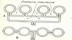
Fig. 49 - In connecting series-type coils, it is
essential to make the connections in such a way that minimum inductance losses
will occur.
Pitch of Coil Windings. In applying multiturn coils for the heating
of steel shafts and other round parts, the pitch of the turn windings will have
a direct relation to the depth of heat penetration. With a find-pitch coil,
such as that illustrated at A in Fig. 50, the magnetic flux penetration will be
more highly concentrated on the surface of the work, with a resultant deeper
layer of heat. With an open-pitch coil, where the space between windings is
increased as at B, the penetration of heat to the surface of the work will be
somewhat less affected by the fact that the magnetic flux spreads out over a
wider area and causes certain losses. Usually in making multiturn coils it is
best to arrange the windings so that the space between turns will not be more
than one-half the thickness of the tubing itself. Beyond this limit, or with
loosely wound coils, non-uniform heating is likely to occur, and unless the
piece being heated is rotated the heat pattern on the work's surface will follow
the spiral of the coil.
When a steel part, such as a shaft, is heated at a comparatively fast rate by
a multiturn coil, there is likely to be a variation in temperature on the work's
surface because of the field set up by the spiral windings. The more open the
windings of the coil, the more pronounced will be the bands of heat, to a point
where the heated surface will follow the spiral form of the coil. For this
reason, the coupling, or spacing from the work to the coil is an important
consideration and, likewise, bears a direct relation to the pitch winding of the
coil.
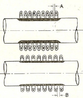
Fig. 50 - Coils provided with fine-pitch
windings have a tendency to throw a deeper layer of heat than those would with
loose windings.
With a coil like the one shown at A in Fig. 51, where the coupling is close
and the pitch winding of the coil loose, the heated zone will take on a bright
and dark pattern, following the exact shape of the coil windings. By increasing
the coil coupling, as at B, the heating becomes more uniform, though it
increases somewhat because of less flux-density transfer to the work's surface.
This heating effect is an important consideration when using multiturn
coils. It is most obvious when the spacing between coil turns is about equal to
the coupling, and diminishes as the tube spacing are reduced, in proportion to
coupling. The best procedure is to rotate the work within the coil so that
uniform heating is assured. This can be done in many cases by hand, if the part
permits, or by a motor-driven spindle, using a speed as low as 25 r.p.m., or
just enough to break up the uneven distribution of current density.
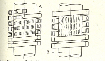
Fig. 51 - Multiturn coils should be correctly
proportioned as to space between windings and their distance from the surface of
the work, so that an even distribution of heat will be assured.
Naturally, the coil spacing around a part to be heated should be uniform,
especially if a uniform distribution of heat is desired. In some cases,
however, a slight amount of eccentricity between
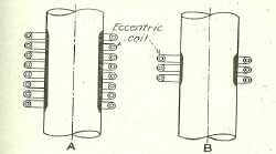
Fig. 52 - If an eccentric coil is used to heat a
section of round steel, the variation in depth of heat penetration will be
proportionately greater with narrow coils than with high.
the work and the coil is not objectionable and may have no effect on the
heated area. This is usually the case when heating a small part and where an
ample amount of power is available. Where the rate of heating may be slower,
however, eccentricity of the coil may produce a variation in heat, the side
nearest the coil receiving the greatest amount.
With a high coil, like that shown at A in Fig. 52, a slight amount of
eccentricity will be hardly noticeable. However, with a narrow coil, as shown
at B, any appreciable amount of eccentricity or unevenness in coupling will be
more apparent in the form of heat variations to the work's surface. This is
quite noticeable in heating such parts as gears, especially when the thickness
is small in proportion to the diameter. Rotation of the work, of course,
offsets irregular heating due to slight
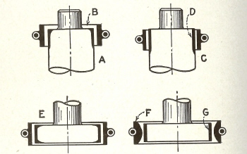 Fig. 53 - When heating coils overlap the edge of
a piece of work, there is likely to be overheating on the end surface. Placing
the coil slightly below the edge will produce a more uniform heat
pattern.
variations in coil couplings, as would be the case with an eccentrically
located inductor.
Heating Effects. When a cylindrical-type heating coil is placed around
the end of a shaft in such a way that it projects over the edge, as indicated at
A in Fig. 53, there will be a pronounced heating over the face as indicated at
B. If, however, the coil is arranged as shown at C, in which case the edge is
even with or slightly below the end of the work, the heat pattern on the surface
will be more uniform, as shown at D.
This same condition exists when heating a disk, or the flanged area of a
piece, as shown at E. The heat pattern will be such that the depth of
penetration will be less in the middle of the blank than at the ends. With some
parts it may be necessary to use a formed coil, as shown at F, with the inner
face made convex. This design provides for a uniform layer heat, as shown at G,
and eliminates the overheating of the edges which might occur with a straight
cylindrical-type coil. These same conditions apply to use of multiturn heating
coils.
In applying heat to a surface which may have a shoulder or flange at each
end, as illustrated in Fig. 54, the spacing of the heating coil in relation to
the various surfaces becomes an important consideration. If the coil were
proportioned as shown at A, where the edges of the coil are closer to the
flanges than the central part is to the body, some heat would be applied to the
edges. This
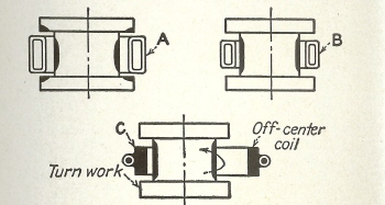
Fig. 54 - In applying heat to flanged surfaces,
the relationship of the coil to the surface of the work is an important
consideration.
would result in the absorption of much of the flux density, so that the body
of the part would receive only a small amount of heat.
For such a surface, therefore, the coil should be made as shown at B,
arranged so that the coil is closest to the body requiring heat. In any case, a
split-type inductor would be required in order that the heat-producing surface
might be properly placed in relation to the surface requiring heat. For such a
part there is the possible use of a larger coil such as shown at C, through
which the work is inserted, and then positioned eccentrically as shown.
Rotation of the work is thus provided. With such a setup the flanges are more
liable to absorb some of the eddy currents, although the body will become more
predominantly heated.
|